Arduino FlightGear Cockpit (AFGcockpit)
Page last changed: August 2022
Contents
- 1. Contents
- 2. What is it?
- 3. Current status
- 4. Features
- 5. Communicating With FG
- 6. PCB Layout
- 7. Source Code
- 8. Pictures
- 9. Version History
- 10. Links (to related information)
What is it?
This is a project which uses the Arduino Duemilanove to control an aeroplane (Cessna) in the Flightgear flightsimulator (FG). The communication between Flightgear and Arduino is with the serial cable (USB).
AFGcockpit stands for Arduino FlightGear cockpit.
Please feel free to contact me if you have any questions or are interested about this.
Current status
Every now and then I get quotes about any updates or progress since 2011. Unfortunately there were none due to "busy life". I eventually started to refactor and modularize the code in 2020, to make it easier for me and also other tinkerers to adjust to their needs. However, in 2021 I didn't have sufficient time to continue and progress once again came to a halt.
I now (in year 2022) decided to upload the code as-is. It is still "work in progress". Anyway, please use this updated code.
You may download the latest source here: wip 2021 tgz
It can handle analog inputs, shift registers, pushbuttons, 7 segment displays.
Hence it is similar to what you can read about below, just the code is cleaner and
easier to overview. The files AFGcockpit.ino and afgcockpit.h are where you should
start looking for configuring your setup.
Enjoy!
Features
The features are (this very list applies to the old code from 2011 which can be downloaded below):
- Two 4051 muxers connected in parallell (only uses 3 pins to control, 2 analog ins). Can now read input from up to 16 different sources (this can be expanded to 6 muxers, ie 48 controls, on the Duemilanove).
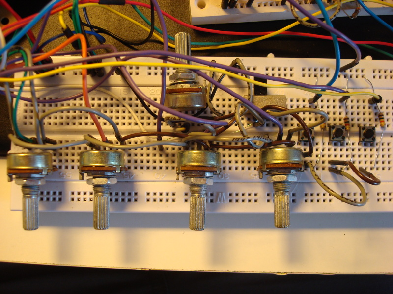
- Aileron, rudder, elevator, elevator trim controlled by rotary pots
- Throttle and flaps (value is converted to 4 discrete steps; 0, 0.3, 0.6, 1) controlled by fader pots
- Breaks (parking, left, right) are controlled with buttons connected to second muxer. Values converted to bools.
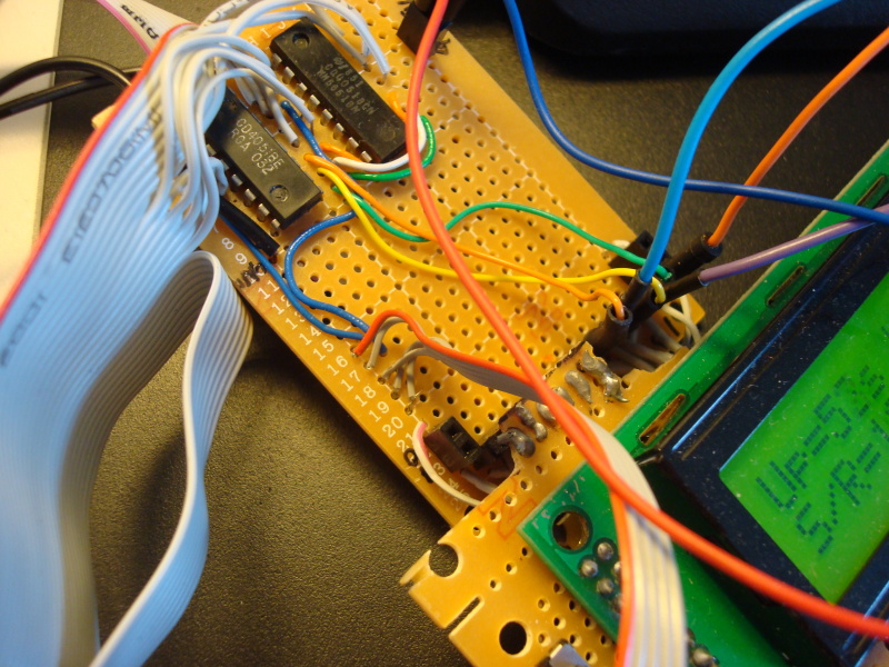
- LEDs and 7 segment displays controlled by 74HC595 shift registers (require 3 pins). Current uses:
- Parking brake LED
- Sync LED (lits when FG and Arduino are not in sync)
- Two 7 segment displays showing the air temp (!)
- ...but can be expanded easily to show more important stuff or build a digital autopilot or comm radio!
- LCD to show different values read from FG. This is mainly for debug and is planned to be removed.
- Switch to enable/disable sending data to FG, in case you want to use mouse, autopilot etc.
- 20 different data read from FG over serial port (ascii format).
- Main loop runs at around 300 times per second if FG send data at 2 Hz and Arduino send at (if necessary maximum) 10 Hz.
Communicating With FG
The communication with FG is carried out over the USB serial port cable. A generic protocol is created, actually two at the moment. One is used for sending and the other for recieving.
FG is started with the following commands:
--generic=serial,out,2,/dev/ttyUSB0,38400,AFGcockpitout
--generic=serial,in,10,/dev/ttyUSB0,38400,AFGcockpitin
On my old (15 year old) Macbook the USB device was /dev/tty.usbserial-A800eIbT.
This will cause FG to read data from the serial port at 10 Hz and send data at 2 Hz at the baud rate of 38400.
Download the protocols:
and place in the protocols folder of FG, ie. $FG_ROOT/Protocol.
PCB Layout
I don't have this, but I have an SVG sketch showing how everything is connected at the moment.
Source Code
Pictures
Yes, the wiring is messy!


Version History
Previous versions on a separate page.
Links (to related information)
fg-arduino is a related project.